


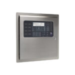
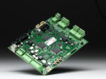
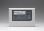
Advanced MxPro 5 – 1 Loop Panel
£804.46 – £937.12
Summary
The MxPro 5 series control panels are supplied with a single loop driver card, 2 onboard sounder circuits, 20 programmable zonal LEDs with slide-in labels, and 25 system LEDs for information purposes. There are also 4 programmable function buttons with LED
indication for confirmation of operation.
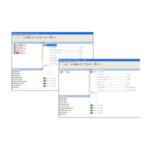
The control panel consists of the latest dual flash-based microprocessor technology combined with a high resolution, high contrast, graphical LCD display and tactile keypad providing a simple ‘select & click’ programming aid for engineer configuration and end user
operation.
Powerful cause-and-effect programming coupled with dynamic zoning, and enhanced trace diagnostics makes the panel suitable for a wide range of site applications from small to large complex multi-area systems. Fully programmable on-site via the on-board alphanumeric keypad, or PC-NeT Configuration Software.
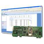
An extensive suite of user-friendly Windows based PC software programs has been developed to enhance your experience when using MxPro 5 series fire panels. The suite incorporates a number of different programmes which include configuration, service, logo and virtual panel tools to allow the flexibility of the equipment to be fully explored.
Simply adding a network card allows the panel to communicate with any other MxPro 5 fire panel, remote terminal, or network peripheral, such as ipGateway™, BMS or graphical interface. The network operates as a true peer-to-peer system and can be configured in a fault tolerant loop or radial format.
Key Features
- 20 programmable zonal / 25 System LEDs.
- Apollo, Argus Vega, Hochiki & Nittan Evolution protocol support.
- Advanced graphical LCD user interface and support for up to 200 fire zones by default allowing full EN54 compliance without additional hardware.
- Dedicated USB & RS232 Serial Port for direct PC or modem connection.
- Installer friendly Auto-learn, Loop Detection and On-board Scope facility.
- Graphical display configurable for virtually any language.
- Robust removable equipment chassis with plug-in connectors for simple fixing and cable termination.
- Integral P-Bus for system expansion via available option cards.
- Ad-NeT peer-to-peer network with up to 2000 zones.
- Approved to BS EN54 part 2, 4 and 13.
FAQ
How Can I Change The Company Logo On MXPro 5 Screen?
This can only be changed with the use of the PC-NET-007 logo software and programming lead.
When adding a 50 or 100 zonal expansion card to a 4 loop panel, will these be in addition to the 20 onboard LEDs?
Yes, this is in addition to the 20.
Similarly does the MxPro 5 network support multiple panels each with different protocols?
Yes, panels on the network can each support different protocols.
Is there a limit the number of short-circuit isolators you can fit onto a MxPro 5 loop?
There are no limits to the amount of isolators installed on a MxPro5 loop. In some cases isolators are in every device, however, we recommend that an isolator should be at least installed every 20 devices and at the start/end of the zonal boundaries of the system (a single fault should not affect more than 1 zone as per your local code of practice, i.e. BS-5839-1) .
Specifications
- Base Technology : Dual flash-based processors with real-time clock, trace diagnostics, programmable languages and character
sets - Display : White backlit 240 x 64 graphical LCD
- LED Indicators : 22 red (1 x Fire, 1 x More Alarms, 20 x Zonal Programmable), 1 green (Power), 13 amber and 12 bi-colour
(Fault & System) - Controls : Alpha numeric keypad permitting navigation, Reset, Mute, Silence, Resound, Evacuate, and 4 x Programmable push buttons
- Protocol :
- Apollo (XP95 / Discovery)
- Argus Vega
- Hochiki ESP
- Nittan Evolution
- Number of Fire Zones : 2000 (200 per individual panel)
- Number of Loops : 1
- Devices Per Loop : Protocol dependent
- Loop Current : 500mA
- On-Board Sounder Circuits : x 1 Amp programmable
- On-Board Relays : 2 x 1 Amp 30v AC/DC programmable(10mA, 5v min) – expandable to 4 using Mxp-507
- Auxiliary Supply : 1 x 24v 500mA
- Programmable Input : 1 x monitored programmable input on-board
- Programmable Key Switch Inputs : 1 x volt free input (standard enc.), 8 x inputs (M, L, D enc.)
- Total Available Output Current : 3A maximum available for loop current + sounder outputs + auxiliary supply
- Mains Supply : 200 – 240v 47-63 Hz AC (+10%, -15% tolerance) 1.0A Max
- Battery Capacity :
- Standard Enclosure : 24v 4 Ah internal (min), 24v, 7 Ah internal (max)
- Medium Enclousre (M) : 24v, 12Ah internal (max)
- Large Enclosure (L) : 24v, 18Ah internal (max)
- Deep Enclosure (D) : 24v, 45Ah
- Charger Current : 1A temperature compensated
- Serial Port : 1 x on-board RS232 connection for PC, modem, IP, or portable printer
- USB Interface : 1 x USB B type connection for PC communication
- Programming : On-board keypad or PC running Windows tools
- Event Log : 5000 event & diagnostic + 500 fire
- Networking : Optional plug-in network card (Mxp-503 – standard, or Mxp-509 – fault-tolerant)
- Printer (optional) : On-board (M, L, D enclosures only)
- Enclosure / Colour : Steel IP30 / RAL7035
- Cable Entry (20mm knockouts) :
- Standard Enclosure : 13 x top & 8 x rear
- Medium Enclousre (M) : 17 x top & 11 x rear
- Large Enclosure (L) : 19 x top & 11 x rear
- Deep Enclosure (D) : 30 x top, 11 rear & 3 bottom
- Size H x W x D mm :
- Standard Enclosure : 340 x 340 x 85
- Medium Enclousre (M) : 340 x 430 x 115
- Large Enclosure (L) : 470 x 450 x 115
- Deep Enclosure (D) : 470 x 450 x 190
- Metalwork Options : Flushing bezel, battery box, utility enclosure, termination enclosure and rack mount
- Approvals : EN 54-2:1998, EN 54-4:1998 & EN 54-13:2005
Downloads
- Datasheet (Adobe PDF)
Additional information
| Weight | 10 kg |
|---|---|
| Protocol | Apollo or Hochiki, Argus Vega, Nittan Evolution |
| Max Loops | |
| Enclosure Size | Small, Medium, Large, Deep |
| Protocol | |
| System Type | |
| Touchscreen |
Related Products
-
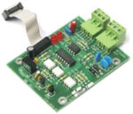
Network Card For Advanced MxPro 5
Advanced- Network card for Advanced MxPro 5 panels.
- Large Ad-NeT+ 200 Panel Network.
- Up to 1.5Km between Control Panels.
- Standard or Fault-Tolerant versions available.
-

Routing Termination Card For Advanced MxPro 5
Advanced- Routing Termination Card For Advanced MxPro 5 panels.
-
Mirrored or Brushed Stainless Steel Finishes For Advanced MxPro5 Panels
Advanced- Clean and stylish.
- Aesthetically pleasing.
- High class look.
-
Sounder Active EOL For Advanced MxPro 5
Advanced- For use with EN54-13 Compliance.
- Supports device removal.
- For use with all MxPro 5 series control panels.
-
Advanced Mx Pro Logo Programming Software
AdvancedEnter a brief description of your product here. This description will be displayed on product list pages.
-
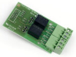
2-Way Programmable Relay Card For Advanced MxPro 5
Advanced- Each output individually programmable.
- Cost effective against ancillary hardware.
- Each output 30V AC/DC, 1 Amp rating.
-
Advanced MXP-532 General Routing Interface
Advanced- Two fire routing outputs.
- Outputs are monitored for open and short circuit wiring issues.
-
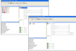
Mx Pro Configuration Software & Lead
Advanced- User Friendly.
- Windows Programming.
- XP & Vista Compatible.
- Remote Diagnostics.
- Product Branding Tool.
- Virtual Control Mode.
- Virtual Diagnostic.
- Mode Cost Effective.
-
PENN Peripheral Expanson Network Node For Advanced MxPro 5
Advanced- Lets you install peripherals in remote locations without an additional panel.
- Network in-built – either Standard or Fault Tolerant.
- Up to 32 Nodes in Standard configuration and Up to 200 Nodes in FT configuration.
-

Remote Battery Temperature Sensor For Advanced MxPro 5
Advanced- Simple to install.
- External battery monitoring.
- For use with all Axis EN series control panels.
-
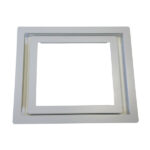
Semi-Flushing Bezel For Advanced MxPro 5 Panels
Advanced- Semi flush fitting for all MxPro 5 panels.
- Picture frame effect for ease of installation 30mm flange for control panels, 20mm for repeaters.
-
Advanced MXP-554 IP Gateway LAN Interface
Advanced- Provides remote access to devices on an Ad Net network..
- Configurable event email notification.
- Compatiable with both Mx-5000 & Mx-4000 series fire panels.
- Available as PCB only or boxed in enclopsure.
- Option of standard or fault-tolerant networks.
-
Advanced MxPro 5 – Remote Terminal (Repeater)
Advanced- Programmable switch input
- Graphical LCD Display
- Ad-NeT/Ad-NeT+ Compatible
- Slide-in Labels
- Small, Robust & compact
- 24V DC Operating voltage
- 3 Year Warranty
- Disable/enable options
-
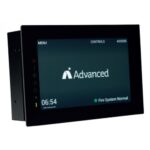
Advanced TouchControl Touch Screen Remote Terminal
Advanced- 2 Part Enclosure for easy fit
- 720P Resolution
- Full Alarm Mapping
- 500 Fire Event Log
- Standard or Fault Tolerant Network Compatible
-
Advanced PC-NET-015 Mx Service Tool Software
Advanced- Retrieval of analogue values, panel meter readings and event logs from the Mx control panels.
-
Advanced MxPro 5 AlarmCalm Button with Buzzer
Advanced- Push button input
- LED output (for use as polling/activated function)
- Mechanically compatible with a single gang UK electrical back box
- Fully addressable device address, sits on loop (Apollo: 1-126, Axis EN:1-240)
- Fully programmable using AlarmCalm software, including verification and second-stage times
- Unique device type recognised as AlarmCalm unit by MxPro 5 FACPs
- Wiring terminations suitable for all Advanced recommended loop cables
- Optional programmable audible buzzer output
- Aimed at reducing unwanted alarms
-
Advanced MxPro 5 Key Switch
Advanced- Enable/disable controls.
- Group isolate to disable I/O across network.
- For use to start/enable a class change.
- Trapped and un-trapped key switches available.
- Control of multi-sensor/device sensitivity mode change.
- Simple to install and configure.
-

Advanced MxPro 5 Access Enable Key Switch
Advanced- Enable/disable controls.
- Group isolate to disable I/O across network.
- For use to start/enable a class change.