Fike Safety: Twinflex Pro 2 Zone, Twinflex Pro 4 Zone & Twinflex Pro 8 Zone

Introduction
The Twinflex Pro Control Panel has 2, 4 or 8 combined 2-wire detection and sounder circuits (or zones) as standard and the 4 zone version will accept a 4z expansion card to increase this to 8 if required.
The front cover and termination PCB should be removed before installation and stored in a safe place to avoid damage. Mount the panel where the controls may be seen and operated without difficulty, where it is accessible for maintenance and at a suitable point of access for the fire services. Ensure that the panel will be clean, dry and free from vibration and temperature excess.
This equipment must be installed and maintained by a qualified and technically competent person and an understanding of Fire Systems Installation & BS5839 is assumed. For more detailed instructions and further details please visit www.discountfiresupplies.co.uk
Power

The 240V AC Mains supply wiring should be fire resistant, between 1mm² & 2.5mm², fed from a double-pole isolating and fused (3A) spur. This should be secure from unauthorised operation and marked “Fire Alarm: Do Not Switch Off”.
The mains supply must be exclusive to the fire panel and the cable should be routed away from the other cables as it enters the control panel adjacent to the mains terminal block on the right hand side.
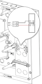
Depending on panel load and standby requirements, two 12 volt sealed lead acid batteries (max 3.4Ah) may be fitted in the housing. The batteries should be wired in series (24V) using the supplied linkwire. Take care not to short circuit the battery terminals.
System Wiring
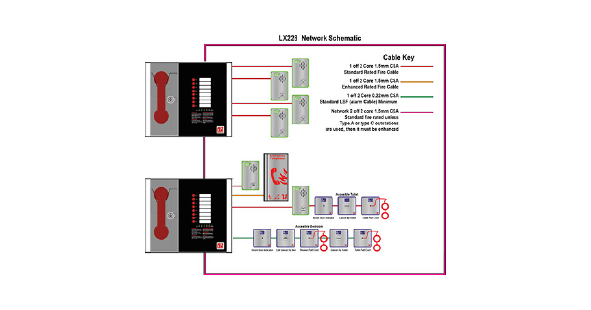
All wiring must be installed to meet BS5839: Pt1: 2013, BS 7671 and other regional standards and legislation. This must be in 2-core 1.5mm² screened fire resistant cable for each circuit. The cable screen must be terminated and connected to earth at the control panel only, connected through at all other positions and protected with PVC earth sleeving to avoid unwanted earth connections.
Detection Zone Wiring
A maximum of 32 Twinflex devices (i.e. Multipoint detectors, Manual Call Points and Sounders) may be fitted to each circuit. Standard conventional devices and other manufacturer’s 2-wire devices are not compatible.

The End of Line monitoring is provided within each device (switch 1) and must only be switched on at the last device on each circuit to allow the cable to be correctly monitored. Do not use a resistor as it is not compatible.

Twinflex Devices
Ensure that you read the instruction sheet for each device as you install it the functionality can be complex. The detector in particular has a number of special features and must be set accordingly with the on-board DIL switch as follows:
| 1 | 2 | 3 | 4 | 5 | 6 | 7 | 8 | |
|---|---|---|---|---|---|---|---|---|
| EOL SIGNAL: ON | ON | |||||||
| EOL SIGNAL: OFF | OFF | |||||||
| DETECTION OFF | OFF | OFF | OFF | |||||
| SMOKE 1: HIGH SENS | ON | OFF | OFF | |||||
| SMOKE 2: STD SENS | OFF | ON | OFF | |||||
| SMOKE 3 LOW SENS | ON | ON | OFF | |||||
| HEAT 1: RoR 58oC | ON | OFF | ON | |||||
| HEAT 2: FIXED 58oC | OFF | ON | ON | |||||
| HEAT 3: FIXED 58oC | ON | ON | ON | |||||
| SMK2/HEAT2 COMBO | OFF | OFF | ON | |||||
| SOUND 0: OFF | OFF | OFF | ||||||
| SOUND1: CONT TONE | ON | OFF | ||||||
| SOUND2: ALT TONE | OFF | ON | ||||||
| SOUND3: SWEEP TONE | ON | ON | ||||||
| LOGICAL LINK: ON | ON | |||||||
| LOGICAL LINK: OFF | OFF | |||||||
| SOUND VOLUME: LOW | OFF | |||||||
| SOUND VOLUME: HI | ON |
Sounder Circuit Wiring
Normally you would use Twinflex 2-wire sounders connected to the zones but two conventional sounder circuits are also provided for conventional 24V sounders.The circuits are rated at max 250mA each. All sounders must be polarised or a fault will be indicated on the sounder circuit.

A 10K End Of Line resistor is supplied with the panel and must be inserted in the last sounder for cable monitoring. The sounder circuits are protected against short circuits with a F315mA fuse and may also be programmed for other functions.
Auxiliary Interface Wiring
- Fire Relay: The volt-free SPCO relay changes in any fire condition. Max 30DC 200mA.
- Fault Relay: This volt-free SPCO relay is normally energised and in a fault condition the output relay turns off to ensure fail-safe operation. This output may be configured to operate as an additional Fire Relay if required. Max 30DC 200mA.
- Monitored Inputs: These 2 inputs may be configured for a number of different functions and must be triggered from a volt-free N/O contact using a 680R trigger resistor and a 3K3 EOL resistor.
- Programmable Input: These 2 un-monitored inputs may be configured for a number of different functions and must be triggered from a volt-free N/O contact.
- Auxiliary Power: This provides a constant un-switched & un-monitored source of power at aprox 30V dc 250mA (fused at F315mA).
- USB-B: This is used for programming if using the PC based OSP software.
Connecting and Testing the System
- Before connecting any circuit, power up the control panel with all of the EOLs fitted directly in their terminals except for the zone circuits. When the 240V AC mains supply and the standby battery are connected there should be no fault indication except for the zones.
- Check the detection zone and sounder circuit wiring for correct continuity and insulation before connecting to the control panel. Do not use a high voltage insulation tester after the devices are connected. Continuity resistance should be approximately 1.2Ω per 100m of cable. Insulation resistance between cores and earth should be greater than 1MΩ.
- Connect the circuits to the panel one at a time, ensuring the EOL is switched on (or connected) at the last device on each circuit and ensure any faults indicated are cleared. Repeat for all circuits. Turn off zones not in use in menus 6: Zone Status.
- Test all detectors, manual call points, sounders, relays etc. for correct operation using the Test mode.
- Test one device in each zone in normal operating mode to ensure all sounders are operational, take sound level readings and log them.
- Measure the current consumption during normal operation and during alarm by putting a suitable current meter in series with the batteries, before removing the 240V AC mains supply. From these readings verify that the battery capacity is suitable.
- Train the End User/Responsible person in the use of the Fire Alarm System including how to operate the controls and how to carry out their weekly test. Ensure the system Log Book is completed and handed over, the zone locations list is filled in and the operation instructions are mounted beside the control panel.
Operating and Programming the Panel


- Level 1: General Controls Enabled – LED: off
- The controls are locked to prevent unauthorised operation.
- Level 2a: User Controls Enabled (from Level 1 press USER enter or turn key on) – LED: on
- Controls: you may silence and sound the alarms, reset the system and silence buzzer.
- Exit: press ESC or turn key off
- Level 2b: Supervisor Controls Enabled (from Level 1 press SUPR enter) – LED: on
- Controls: you may silence and sound the alarms, reset the system and silence buzzer.
- Menus: Use UP and DOWN arrows to choose option then enter to select
- Exit: press ESC or turn key on and off again.
- Level 3: Engineer (from level 1 press ENGR enter) – Controls Enabled LED: flash
- Controls: you may silence and sound the alarms, reset the system and silence buzzer.
- Menus: Use UP and Down arrows to choose option then enter to select. Ensure that the WRITE ENABLE switch is ON before any changes are made.
- Exit: press ESC or turn key on & off again.
- User:
- View Current Events: Fires / Faults / Disables / Warnings
- Test Modes: Controls & Display / Zones
- Supervisor: as User +:
- Enable / Disable: Rem Fire / Sounders / Zones / Network
- Set Time and Date
- View Logs
- Engineer: as Supr +:
- Zones: Status / Desc / Mode
- Alarm Configuration: Zone type / Conf type / Delay
- Alarm Delay: Zone OPs / Relays / Mon Ops / Time / Origin
- Panel Details: Buzzer / Codes / Software / Panel ID / Timers
- Panel I/O: Prog IPs / Mon IPs / Relays
- Network: Presence / Configure / IPs / Transmit / Modules