Zeta Alarm Systems: Simplicity 64, 126, 252
Introduction
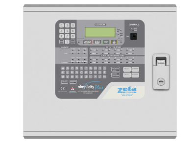
The Simplicity Control Panel has 1 or 2 addressable device loop circuits which will accommodate 64, 126 or 252 devices according to the model selected. The panel is compatible with both Fyreye MKI and MKII loop protocols (which are both menu selectable depending on the devices you use).
The front door and PCBs should be removed before installation and stored in a safe place to avoid damage. Mount the panel where the controls may be seen and operated without difficulty, where it is accessible for maintenance and at a suitable point of access for the fire services. Ensure that the panel will be clean, dry and free from vibration and temperature excess.
This equipment must be installed and maintained by a qualified and technically competent person and an understanding of Fire Systems installation and BS5839 is assumed. For more detailed instructions and further details please visit www.discountfiresupplies.co.uk.
Power
 The 240V AC Mains supply wiring should be fire resistant, between 1mm² and 2.5mm², fed from a double-pole isolating and fused (3A) spur. This should be secure from unauthorized operation and marked “Fire Alarm: Do Not Switch Off”.
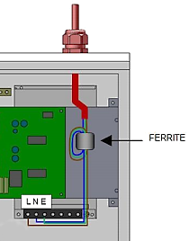
The mains supply must be exclusive to the fire panel and the cable should be routed away from the other cables as it enters the control panel adjacent to the mains terminal block on the right hand side.
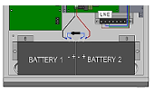 Depending on panel load and standby requirements two 12 volt sealed lead acid batteries (7Ah or 12Ah) may be fitted in the housing. The batteries should be wired in series (24V) using the supplied link-wire. Take care not to short circuit the battery terminals.
System Wiring
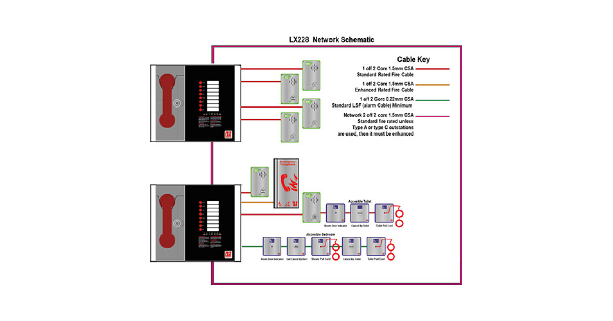
All wiring must be installed to meet BS5839: Pt1: 2013, BS 7671 and other regional standards and legislation. This must be in 2-core 1.5mm² screened fire resistant cable for each circuit. The cable screen must be terminated and connected to Earth at the control panel only, connected through at all other positions and protected with PVC earth sleeving to avoid unwanted earth connections.
Addressable Device Loop Wiring
The addressable device loop has a capacity for up to 64 or 126 addresses (according to the model) which may be detectors, sounders, manual call points or interface modules, and may be located at any point on the circuit. A maximum of 64 indoor sounders are permitted per loop. The circuit must be installed as a complete loop returning to the control panel. In order to prevent loss of all devices during a possible cable fault loop isolators should be installed at every zone boundary. These may be built into one of the addressable devices such as the MCP or I/O modules.
Setting Device Addresses
The unique address is set using the DIL switch mounted on each device with a binary code where switch ON = binary ‘0’ and switch OFF = binary ‘1’. Binary weighting starts from switch 1 in the sequence 1, 2, 4, 8, 16, 32, 64, 126 (i.e. address 5 = 1, 0, 1, 0, 0, 0, 0 = OFF, ON, OFF, ON, ON, ON, ON). Certain types of sounder do not require an address, i.e. ‘Associated’ and ‘Common’ sounders. To simplify setup the loop addresses are assigned to zones, Z1 = address 1-16, Z2 = address 17-32 etc., but the zone boundaries may be altered in the configuration menu. Please consult the device instruction manual for further information.
Auxiliary Interface Wiring
- Fire Relay: The volt-free SPCO relay changes in any fire condition. Max 30DC 500mA.
- Fault Relay: This volt-free SPCO relay is normally energised and in a fault condition the output relay turns off to ensure fail-safe operation. Max 30DC 500mA.
- Class Change: This input allows monitoring of a N/O volt-free contact and causes all alarm outputs to be activated. The input is non-latching and will reset when the trigger is removed.
Connecting and Testing the System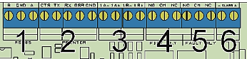
- Before connecting any circuit power up the control panel. When the 240V AC mains supply and the standby battery are connected there should be no fault indication.
- Check the device loop circuit wiring for correct continuity and insulation before connecting to the control panel. Do not use a high voltage insulation tester after the devices are connected. Continuity resistance should be approximately 1.2 Ω per 100m of cable. Insulation resistance between cores and earth should be greater than 1M Ω.
- Connect the device loop cables to the terminals in the control panel select the option to CONFIGURE LOOPS (it will appear automatically if it is a new ‘blank’ panel – see below). Verify that all devices are correctly identified by the panel and enter the device text.
- Test all detectors, manual call points, sounders, relays etc. for correct operation using the One Man Test mode.
- Test one device in each zone in normal operating mode to ensure all sounders are operational, take sound level readings and log them.
- Measure the current consumption during normal operation and during alarm by putting a suitable current meter in series with the batteries, before removing the 240V AC mains supply. From these readings verify that the battery capacity is suitable.
- Train the End User/Responsible Person in the use of the Fire Alarm System including how to operate the controls and how to carry out their weekly test. Ensure the system Log Book is completed and handed over, the zone locations list is filled in and the operation instructions are mounted beside the control panel.
Operating and Programming the Panel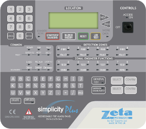
Level 1: General Access On
LED: Off
Controls: The controls are locked to prevent unauthorised operation.
Level 2: User Controls Access On (turn key on)
LED: On
Controls: You may start and stop the sounders, silence the buzzer and reset the system
Exit: Turn key off.
Level 2: User Configuration LCD Indication of Menu (turn key on and press ENTER)
1: Loop Contents: View quantity of each device type configured onto the loop
2: Device Status: View the status of an individual device: normal/fault/alarm, analogue values, label
3: Event Logs: View alarms, faults, system and all events
Exit: Turn key off
Level 3: Engineer LCD Indication of Menu (from level 2 press 369)
4: Configure Loops: Configure the loop with all current devices/addresses
5: Edit Device: Inc. device label, LED on, sounder on/off, alarm verification, disablement, I/O functions
6: Config System:
6.1: Clock: Set time and date
6.2: Zones: Change zone allocation boundaries
6.3: Alarm Operation: Det, MCP, Sounders, Bases, I/O: zonal or common alarm and other settings
6.4: Timing: Zonal to common and alarm verification times
6.5: Misc: Language, software version, loop protocol
6.6: Reset: Logs, zones, panel, devices, all: returns settings to default
Exit: Turn key off.